
Agilent USB-GPIB 82357B on Ubuntu24.04, 26.04
1st version 10/07/2026
General
This guide describes how to install and use an Agilent USB-GPIB Interface 82357B
adapter on Ubuntu 24.04 and Ubuntu 26.04 using Linux-GPIB 4.3.7.
The setup procedure for this adapter is almost the same as that for the NI GPIB-USB-HS when using Linux-GPIB. However, the procedure is slightly shorter because this adapter does not require an additional patch or configuration of gpib.conf.
Test Configurations
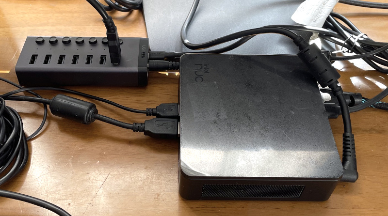
Intel NUC13ANK
- Intel Core i5-1340P – 16 GB RAM – Intel Iris Xe Graphics (onboard)
- Ubuntu 24.04.4 LTS, clean installation
- Ubuntu 26.04.1 LTS, clean installation
HP ENVY 17t-s100
- Intel Core i7-6700HQ – 16 GB RAM – Intel HD Graphics 530
- Ubuntu 24.04.4 LTS
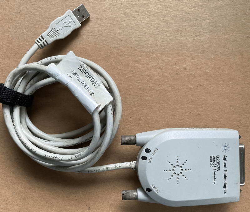
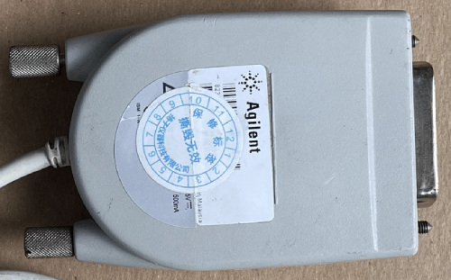
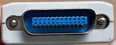
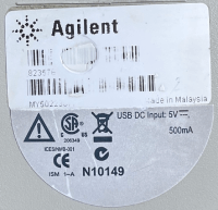
USB-GPIB Adapter: Agilent USB-GPIB Interface 82357B
This adapter was purchased as a used item from an eBay seller named “zecenke-5” for $50 in June 2026.
Linux-GPIB Drivers and Utilities Installation
1. Linux-GPIB Drivers and Utilities Installation
sudo apt update
sudo apt upgrade
sudo apt install build-essential
sudo apt install python3-setuptools
sudo apt install python3-dev
sudo apt install libboost-python-dev
Reboot Ubuntu before continuing:
sudo reboot
Check the currently running kernel:
uname -r
The kernels used for the tests described here were:
Ubuntu 24.04.4: 7.0.0-31-generic
Ubuntu 24.04.4: 7.0.0-34-generic
Ubuntu 26.04.1: 7.0.0-31-generic
Disconnect the GPIB adapter’s USB cable from the PC before starting the installation.
2. Download the Linux-GPIB Driver Package from SourceForge
Linux-GPIB download page:
https://sourceforge.net/projects/linux-gpib/files/linux-gpib%20for%203.x.x%20and%202.6.x%20kernels/
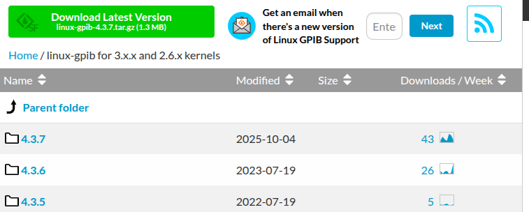
Download Linux-GPIB 4.3.7.
Then confirm that the downloaded file is present:
cd ~/Downloads
ls -al linux-gpib-4.3.7.tar.gz
Example:
-rw-rw-r-- 1 mm mm 1309937 Sep 6 15:11 linux-gpib-4.3.7.tar.gz3. Copy the Package to /opt and Extract It
sudo cp linux-gpib-4.3.7.tar.gz /opt/
cd /opt/
sudo tar -xzf linux-gpib-4.3.7.tar.gz
cd linux-gpib-4.3.7/
ls -al
The package contains separate kernel and user-space archives:
-rw-r--r-- 1 mm users  213606 Oct 5 2025 linux-gpib-kernel-4.3.7.tar.gz
-rw-r--r-- 1 mm users 1095172 Oct 5 2025 linux-gpib-user-4.3.7.tar.gz
-rw-r--r-- 1 mm users    4175 Oct 5 2025 README.txt
Extract both archives:
sudo tar -xzf linux-gpib-kernel-4.3.7.tar.gz
sudo tar -xzf linux-gpib-user-4.3.7.tar.gz
✎ After a Linux kernel update
The Linux-GPIB kernel drivers may need to be rebuilt after a kernel update. A driver built for the previous kernel is not automatically available for a newly installed kernel.
If GPIB suddenly stops working after a kernel update, first check the currently running kernel:
uname -r
Then check whether the 82357A GPIB driver (the driver name is 82357a, not 82357b) has been installed for that kernel:
find /lib/modules/$(uname -r) -name "agilent_82357a.ko*"
Linux kernel modules are installed separately for each kernel version under /lib/modules/.
If agilent_82357a.ko is not found for the currently running kernel, repeat the installation procedure from Section 4. Install the Linux Kernel Headers onward.
4. Install the Linux Kernel Headers
sudo apt install linux-headers-$(uname -r)
5. Build and Install the Kernel Drivers
Move to the kernel source directory:
cd /opt/linux-gpib-4.3.7/linux-gpib-kernel-4.3.7/
Build and install the drivers:
make clean
make
sudo make install
During installation, drivers for the supported GPIB interfaces are installed. Among them, you should see a line similar to:
INSTALL /lib/modules/7.0.0-31-generic/gpib/agilent_82357a/agilent_82357a.ko
The exact kernel version in the path will depend on the output of
uname -r
6. Install the User-Space Libraries and Utilities
Move to the user-space source directory:
cd /opt/linux-gpib-4.3.7/linux-gpib-user-4.3.7/
Configure, build, and install:
./configure --sysconfdir=/etc
make
sudo make install
This installs the Linux-GPIB user-space library and utilities, including programs such as ibtest and ibterm.
7. Install the Python Binding
7-1. Make libgpib.so.0 Available to the PyVISA Backend
In my environment, the following symbolic link was required so that the
PyVISA @py backend could locate libgpib.so.0:
sudo ln -s /usr/local/lib/libgpib.so.0 /lib/libgpib.so.0
✎ Note
This symbolic link was required in the systems tested for this guide. Depending on your library configuration, it may not be necessary on every Ubuntu installation.
7-2. Install the Linux-GPIB Python Binding
Move to the Python directory in the Linux-GPIB source tree:
cd /opt/linux-gpib-4.3.7/linux-gpib-user-4.3.7/language/python
ls -al
Confirm that setup.py is present, and install the binding:
sudo python3 setup.py install
8. Install PyVISA for Python Instrument Control
sudo apt update
sudo apt install python3-pyvisa
Check the PyVISA installation:
pyvisa-info
If the Linux-GPIB backend has been installed correctly, the final part of the output should include lines similar to:
GPIB INSTR: Available via Linux GPIB (b'4.3.7')
GPIB INTFC: Available via Linux GPIB (b'4.3.7')
Reboot Ubuntu before continuing:
sudo reboot
9. Connect the Agilent 82357B USB Cable and Check Its Status
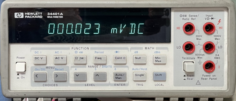
Connect the Agilent 82357B to the HP 34401A and turn on the HP 34401A.
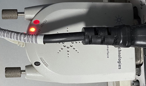
At this point, only the FAIL (red) LED is illuminated. This is normal because the firmware has not yet been loaded.
Check USB Detection
lsusb | grep GPIBBus 003 Device 005: ID 0957:0518 Agilent Technologies, Inc. 82357B GPIB Interface
Confirm that the Agilent 82357B appears in the USB device list.
10. Install fxload
Install fxload before setting up the firmware:
sudo apt install fxload11. Install the Firmware
11-1. Download and Extract the Firmware Package
Move to /opt and download the firmware package:
cd /opt
sudo wget --content-disposition --no-check-certificate http://linux-gpib.sourceforge.net/firmware/gpib_firmware-2008-08-10.tar.gz
Extract the archive:
sudo tar -xvf gpib_firmware-2008-08-10.tar.gz
11-2. Copy the Firmware Files
Note that the firmware directory for the 82357B is named agilent_82357a:
cd /opt/gpib_firmware-2008-08-10/agilent_82357a/
sudo cp -r * /usr/local/share/usb/agilent_82357a/
After installing the firmware files,
Disconnect the GPIB adapter’s USB cable from the PC and reconnect it.
12. Configure GPIB Device Permissions
By default, /dev/gpib0 may be accessible only by root. Configure a udev rule so that Linux-GPIB applications, including ibtest and Python programs, can access the device without sudo.
12-1. Check Membership in the plugdev Group
Run:
groups
In my environment, plugdev was already listed:
mm adm cdrom sudo dip plugdev users lpadmin
If plugdev is already listed, skip the next usermod command.
If plugdev is not listed, add the current user to the group.
sudo usermod -aG plugdev $USERLog out and log back in after running this command.
12-2. Create a udev Rule
Open a new rule file:
sudo gedit /etc/udev/rules.d/99-gpib.rules
Add the following line:
KERNEL=="gpib[0-9]*", GROUP="plugdev", MODE="0660"
Save the file, and reload the udev rules:
sudo udevadm control --reload-rules
sudo udevadm trigger
Disconnect the GPIB adapter’s USB cable from the PC and reconnect it.
Check the permissions:
ls -l /dev/gpib0
In my environment, the result was:
crw-rw---- 1 root plugdev 160, 0 Sep 7 12:07 /dev/gpib0
If plugdev is shown as the group and your user belongs to plugdev, the device can be accessed without sudo.
13. Final Check
13-1. Check USB Detection
lsusb | grep GPIB
Example:
Bus 003 Device 017: ID 0957:0718 Agilent Technologies, Inc. 82357B ()
Important: Check the USB device ID carefully. After loading the firmware with fxload and reconnecting the USB cable, the device ID should change from 0957:0518 to 0957:0718.
If lsusb shows 0957:0718 and only the READY LED is illuminated, the 82357B is ready for use.
13-2. Check the LEDs on the 82357B
Disconnect the GPIB adapter’s USB cable from the PC and reconnect it.
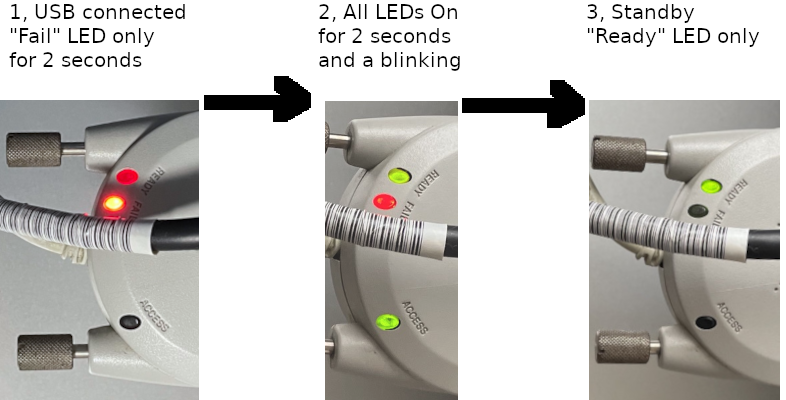
The LED should be as follows.
Immediately after the USB cable is connected, only the FAIL (red) LED lights up for a few seconds.
Then, the READY (green), FAIL (red), and ACCESS (green) LEDs all remain lit for about 10 seconds.
Finally, only the READY LED remains lit, indicating the normal standby state in which the device is ready for use.
The Linux-GPIB driver, user-space utilities, firmware, and device permissions are now configured, and the 82357B is ready for an actual communication test.
The next section uses the Linux-GPIB utilities ibtest and ibterm to communicate with an HP 34401A.
Utility Applications
The Linux-GPIB installation includes several command-line utilities.
Before testing with Python, it is useful to confirm basic GPIB communication with ibtest and ibterm.
The examples below use an HP 34401A at GPIB address 13.
1. Test Communication with ibtest
1-1, Operation
ibtest, included with Linux-GPIB, provides a simple way to verify communication with a GPIB instrument without writing a program.
Start ibtest:
ibtest
For the example used in this guide, enter the following selections:
d— open a device, not a GPIB interface board13— GPIB address of the HP 34401Aw— write a command to the instrument*IDN?— query the instrument identificationr— read the response100— maximum number of bytes to read
A typical session is shown below:
Do you wish to open a (d)evice or an interface (b)oard?
    (you probably want to open a device): d
enter primary gpib address for device you wish to open [0-30]: 13
trying to open pad = 13 on /dev/gpib0 ...
After the device has been opened, select w:
: w
enter a string to send to your device: *IDN?
Then select r and specify the maximum number of bytes to read:
: r
enter maximum number of bytes to read [1024]: 100
trying to read 100 bytes from device...
received string: 'HEWLETT-PACKARD,34401A,0,7-5-2
'
Number of bytes read: 31
This confirms that the adapter can send a GPIB command to the instrument and receive its response.
Enter q to exit ibtest.
1-2. Useful HP 34401A Commands for ibtest
| Command | Description | Read required? |
|---|---|---|
*IDN? | Queries the instrument identification information HEWLETT-PACKARD,34401A,0,7-5-2 | Yes |
MEAS:VOLT:DC? | Measures DC voltage and returns the measured value received string: ‘+5.25970000E-05’ | Yes |
MEAS:VOLT:AC? | Measures AC voltage and returns the measured value received string: ‘+1.80423900E-03’ | Yes |
MEAS:RES? | Measures resistance and returns the measured value received string: ‘+1.00052360E+06’ | Yes |
CONF:VOLT:DC | Configures the DMM for DC voltage measurement | No |
CONF:VOLT:AC | Configures the DMM for AC voltage measurement | No |
CONF:RES | Configures the DMM for resistance measurement | No |
READ? | Performs a measurement using the current configuration | Yes |
*RST | Resets the instrument to its default settings | No |
*CLS | Clears the instrument status registers | No |
For example, a DC-voltage measurement can be performed as follows:
w
MEAS:VOLT:DC?
r
100
Example response:
received string: '+3.73280000E-05'
The installation described in the previous section was tested again using ibtest. Both *IDN? and MEAS:VOLT:DC? returned valid responses from the HP 34401A.
Other command sequences tested in this environment included:
w, MEAS:VOLT:AC?, r, 100  ---> -4.83986000E-04
w, MEAS:RES?,     r, 100  ---> +1.00052360E+06
w, CONF:VOLT:DC, w, READ?, r, 100 ---> -7.02526000E-04
w, READ?, r, 100 ---> -5.60173000E-04
w, READ?, r, 100 ---> -5.28759000E-04
w, READ?, r, 100 ---> -4.95879000E-04
2. Test Communication with ibterm
ibterm is another Linux-GPIB utility for communicating interactively with a GPIB instrument. It is more convenient than ibtest when you simply want to type instrument commands and view the responses.
Start ibterm with the GPIB address of the instrument:
ibterm -d 13
where 13 is the GPIB address of the HP 34401A.
A typical startup message is:
Attempting to open /dev/gpib0
pad = 13, sad = 0, timeout = 10, send_eoi = 1, eos_mode = 0x0000
Commands can then be entered directly:
ibterm>*IDN?
HEWLETT-PACKARD,34401A,0,7-5-2
ibterm>MEAS:VOLT:DC?
ibterm>
2.36290000E-05
ibterm>MEAS:VOLT:AC?
ibterm>
ibterm>
+2.07990600E-03
ibterm>MEAS:RES?
ibterm>
+9.90000000E+37
ibterm>CONF:VOLT:DC
ibterm>READ?
ibterm>
+1.49352000E-04
ibterm>READ?
ibterm>
+1.00994000E-04
✎ Notes from my tests with ibterm:
With the Agilent 82357B, *IDN? returned a response immediately after pressing [Enter] once. Other commands also worked, but some required additional [Enter] presses before the response appeared. In my tests, some commands returned a response after the second [Enter], while others required a third [Enter].
This behavior was consistently observed with the Agilent 82357B in my test environment. It should be treated as an observation from this setup rather than as a general requirement for all 82357B adapters.
At this point, basic GPIB communication has been verified using the Linux-GPIB utilities. The next section tests GPIB communication using Python and PyVISA.
Test with Python and PyVISA
1. Test GPIB Interactively with Python
Before creating a Python script, communication can be checked directly from the Python interactive prompt.
Start Python:
python3
At the >>> prompt, enter or paste:
import pyvisa
rm = pyvisa.ResourceManager()
inst = rm.open_resource("GPIB0::13::INSTR")
print(inst.query("*IDN?"))
inst.close()
rm.close()
For the HP 34401A used in this example, the response is:
HEWLETT-PACKARD,34401A,0,7-5-2
This confirms that PyVISA can communicate with the instrument through Linux-GPIB.
To leave the Python interactive mode:
quit()
✎ Note
GPIB0 is the VISA interface name, while 13 is the GPIB address of the instrument. Change the address to match your instrument.
2. Python CLI Application for One HP 34401A
This first program reads the instrument ID and then measures DC voltage five times.
2-1. File
File name: dmm1-cli.py
The example programs are available from:
https://github.com/moriyasum/GPIB
Change adr and, if necessary, interface in the source code to match your system.
2-2. Run the Program
python3 ./dmm1-cli.py
2-3. Example Output
Interface:  GPIB0 , GPIB address:  13
Instrument ID:  HEWLETT-PACKARD,34401A,0,7-5-2
0 DC Voltage = +3.65830000E-05 V
1 DC Voltage = +5.06870000E-05 V
2 DC Voltage = +4.25880000E-05 V
3 DC Voltage = +5.31860000E-05 V
4 DC Voltage = +4.21300000E-05 V
2-4. Python Source Code
import pyvisa
import time

# GPIB address and interface number
adr = "13"
interface = "GPIB0"

# Open VISA
rm = pyvisa.ResourceManager()
dmm = rm.open_resource(f"{interface}::{adr}::INSTR")
dmm.timeout = 5000

# Read instrument ID
print("Interface: ", interface, ", GPIB address: ", adr)
print("Instrument ID: ", dmm.query("*IDN?").strip())

for i in range(5):
    # Configure the DMM for DC voltage measurement
    dmm.write("CONF:VOLT:DC")

    # Take a measurement
    value = dmm.query("READ?")
    print(i, "DC Voltage =", value.strip(), "V")

    time.sleep(2)

# Close the instrument and Resource Manager
dmm.close()
rm.close()
The VISA resource string is constructed with an f-string:
f"{interface}::{adr}::INSTR"
With interface = "GPIB0" and adr = "13", this becomes:
GPIB0::13::INSTR
3. Simple Python GUI Application for One HP 34401A
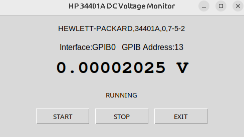
The next example adds a small Tkinter GUI. It displays the instrument ID, GPIB interface and address, measured DC voltage, and START / STOP / EXIT buttons.
3-1. File
File name: dmm1-gui.py
Download location:
https://github.com/moriyasum/GPIB
✎ Change the GPIB address in the source code to match your instrument.
3-2. Run the Program
Install Tkinter for the GUI:
sudo apt install python3-tk
Run program:
python3 ./dmm1-gui.py
3-3. Example GUI
3-4. Python Source Code
import tkinter as tk
import pyvisa

# GPIB address and interface number
adr = "13"
interface = "GPIB0"

# Open VISA
rm = pyvisa.ResourceManager()
dmm = rm.open_resource(f"{interface}::{adr}::INSTR")
dmm.timeout = 5000

# Read instrument ID
idn = dmm.query("*IDN?").strip()

# Configure DC voltage measurement mode
dmm.write("CONF:VOLT:DC")

# GUI
root = tk.Tk()
root.title("HP 34401A DC Voltage Monitor")
root.geometry("500x250")

running = False

voltage_text = tk.StringVar(value="-------- V")
status_text = tk.StringVar(value="STOPPED")


def measure():
    if not running:
        return

    try:
        voltage = float(dmm.query("READ?"))
        voltage_text.set(f"{voltage:.8f} V")
        status_text.set("RUNNING")
    except Exception as e:
        status_text.set("ERROR: " + str(e))

    if running:
        root.after(500, measure)


def start():
    global running

    if not running:
        running = True
        measure()


def stop():
    global running

    running = False
    status_text.set("STOPPED")


def close():
    dmm.close()
    rm.close()
    root.destroy()


tk.Label(
    root,
    text=idn,
    font=("Arial", 11)
).pack(pady=15)

tk.Label(
    root,
    text=f"Interface:{interface}   GPIB Address:{adr}",
    font=("Arial", 12)
).pack()

tk.Label(
    root,
    textvariable=voltage_text,
    font=("Courier", 28, "bold")
).pack(pady=15)

tk.Label(
    root,
    textvariable=status_text
).pack()

button_frame = tk.Frame(root)
button_frame.pack(pady=15)

tk.Button(
    button_frame,
    text="START",
    command=start,
    width=10
).pack(side="left", padx=5)

tk.Button(
    button_frame,
    text="STOP",
    command=stop,
    width=10
).pack(side="left", padx=5)

tk.Button(
    button_frame,
    text="EXIT",
    command=close,
    width=10
).pack(side="left", padx=5)

root.protocol("WM_DELETE_WINDOW", close)

root.mainloop()
4. Python CLI Application for Three HP 34401A Multimeters
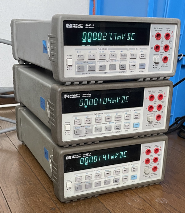
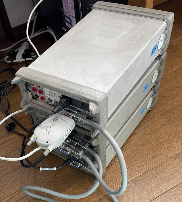
The next example controls three HP 34401A multimeters connected to the same GPIB bus.
The GPIB addresses used in this example are:
- DMM 1: address 11
- DMM 2: address 12
- DMM 3: address 13
4-1. File
File name: dmm3-cli.py
Download location:
https://github.com/moriyasum/GPIB
✎ Change the GPIB address to match your instrument.
4-2. Run the Program
python3 ./dmm3-cli.py
4-3. Example Output
Interface:GPIB0
Instrument 1: Addr=11  HEWLETT-PACKARD,34401A,0,4-1-1
Instrument 2: Addr=12  HEWLETT-PACKARD,34401A,0,5-1-1
Instrument 3: Addr=13  HEWLETT-PACKARD,34401A,0,7-5-2
0 DC Volt: 11= +1.87790000E-05 V, 12= +2.36160000E-05 V, 13= +5.30810000E-05 V
1 DC Volt: 11= +2.15320000E-05 V, 12= +2.77230000E-05 V, 13= +5.66400000E-05 V
2 DC Volt: 11= +2.97650000E-05 V, 12= +3.68070000E-05 V, 13= +4.06650000E-05 V
4-4. Python Source Code
import pyvisa
import time

# GPIB addresses and interface number
adr1 = "11"
adr2 = "12"
adr3 = "13"
interface = "GPIB0"

# Open VISA
rm = pyvisa.ResourceManager()

dmm1 = rm.open_resource(f"{interface}::{adr1}::INSTR")
dmm1.timeout = 5000

dmm2 = rm.open_resource(f"{interface}::{adr2}::INSTR")
dmm2.timeout = 5000

dmm3 = rm.open_resource(f"{interface}::{adr3}::INSTR")
dmm3.timeout = 5000

print(f"Interface:{interface}")

# Read instrument IDs
print(f"Instrument 1: Addr={adr1} ", dmm1.query("*IDN?").strip())
print(f"Instrument 2: Addr={adr2} ", dmm2.query("*IDN?").strip())
print(f"Instrument 3: Addr={adr3} ", dmm3.query("*IDN?").strip())

# Configure all three DMMs for DC voltage measurement
dmm1.write("CONF:VOLT:DC")
dmm2.write("CONF:VOLT:DC")
dmm3.write("CONF:VOLT:DC")

for i in range(10):
    value = dmm1.query("READ?")
    print(i, "DC Volt:", adr1 + "=", value.strip(), "V, ", end="")

    value = dmm2.query("READ?")
    print(adr2 + "=", value.strip(), "V, ", end="")

    value = dmm3.query("READ?")
    print(adr3 + "=", value.strip(), "V")

    time.sleep(0.5)

# Close the instruments and Resource Manager
dmm1.close()
dmm2.close()
dmm3.close()
rm.close()
5. Python GUI Data Logger for Three HP 34401A Multimeters
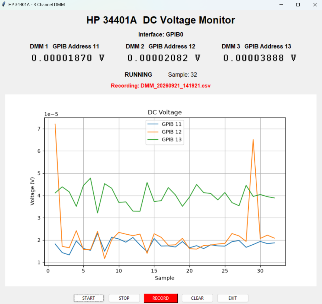
The final Python example expands the three-instrument program into a GUI data logger with real-time display, graphing, and recording.
5-1. File
File name: dmm3-gui-graph-record.py
The full source code is available here:
https://github.com/moriyasum/GPIB/blob/main/dmm3-gui-graph-record.py
✎ Change the GPIB address to match your instrument.
5-2. Run the Program
Install Tkinter for the GUI:
sudo apt install python3-tk
Install Matplotlib for graphing:
sudo apt install python3-matplotlib
Run program:
python3 ./dmm3-gui-graph-record.py
5-3. Example GUI
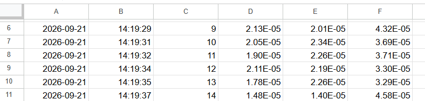
Example of a recorded data file:
5-4. Python Source Code
Because this program is considerably longer than the previous examples, the complete source code is maintained on GitHub rather than duplicated here:
https://github.com/moriyasum/GPIB/blob/main/dmm3-gui-graph-record.py
The progression of the examples is therefore:
interactive Python → one-DMM CLI → one-DMM GUI →
three-DMM CLI → three-DMM GUI/data logger
This makes it possible to verify each layer of the system before moving to the next one.
USB Connection and Detection Test with Three HP 34401A Multimeters
After confirming operation with the three-DMM Python program, I also tested the NI GPIB-USB-HS with different USB ports on the Intel NUC13ANK.
| USB port | Hot plug (Note) | Hot plug through a powered USB hub | Connected before power-on |
|---|---|---|---|
| USB 3.2 | GOOD | GOOD | GOOD |
| USB 2.0 | GOOD | GOOD | GOOD |
| Thunderbolt 4 | GOOD | GOOD | GOOD |
In these tests, the adapter was detected and communication with the three HP 34401A multimeters worked in all of the connection methods shown above.
✎ Observation during USB hot-plugging
During testing, the HDMI monitor frequently went black for a few seconds at the moment a USB plug was connected directly to the NUC.
On one occasion, Ubuntu also rebooted unexpectedly.
I initially tried a powered USB hub, but a similar event could occur when the powered hub itself was connected to the NUC.
In this test setup, the powered hub did not eliminate the problem.
Ground-Potential Difference Observed in My Test Setup
Further investigation showed a substantial AC potential difference between the NUC chassis/USB ground and the measurement-equipment chassis in my particular setup.
This malfunction caused by the electrical transient during connection occurred only on the NUC in this experiment and did not occur on the Envy or EliteDesk systems.
A powered USB hub did not eliminate the issue in this setup.
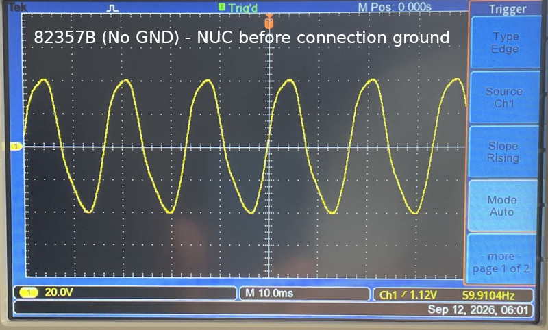
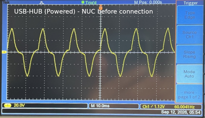
In my test setup, after confirming that the chassis/ground points could be safely connected, equalizing their potentials eliminated the USB-connection problem.
Ground/chassis connection used in this test setup:
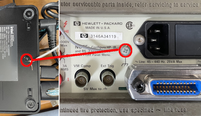
⚠️ Warning: Do not treat the chassis connection shown above as a general solution.
The connection was made only after checking the particular equipment used in this test. Do not connect the chassis or ground terminals of two devices together unless you have first confirmed that the connection is electrically safe.
In particular, do not make such a connection between equipment connected directly to the AC mains, power equipment, or equipment with an unknown grounding or isolation configuration. A large potential difference or fault current could flow through the added wire, the GPIB cable, or the computer, creating a risk of equipment damage or electric shock.
The important point from this test is that the USB/GPIB software itself was not the only possible cause of connection instability. In this particular setup, an electrical potential difference between the connected equipment was associated with the USB hot-plug symptoms.
Conclusion
The Agilent 82357B used in this project was successfully operated on Ubuntu with Linux-GPIB 4.3.7 without requiring any adapter-specific source-code patch.
Communication was verified with Linux-GPIB utilities, PyVISA, and the same Python programs used with the NI GPIB-USB-HS, including examples using one and three HP 34401A multimeters. The three-instrument GUI/data-logger also operated successfully through the 82357B.
In this test environment, the 82357B therefore provided a relatively straightforward Linux-GPIB configuration, while allowing the same Python measurement programs to be used with either GPIB adapter.